
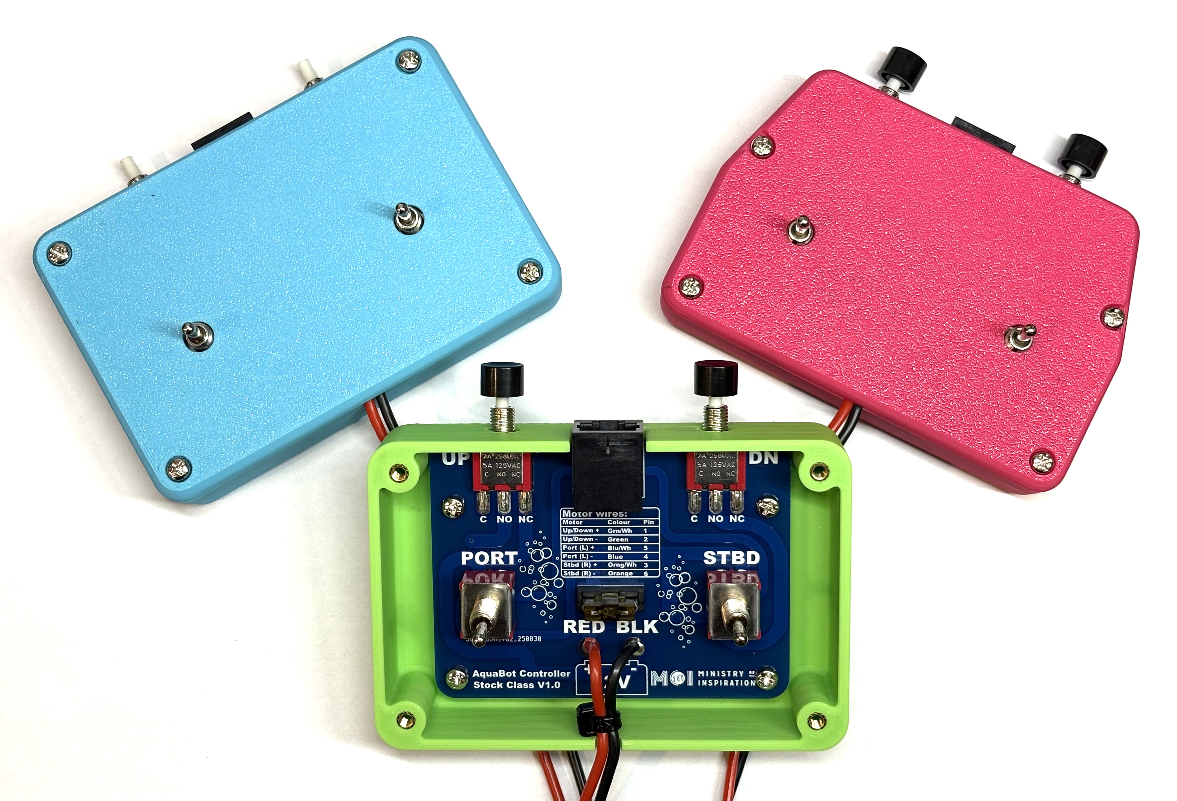
What's in Your Kit?
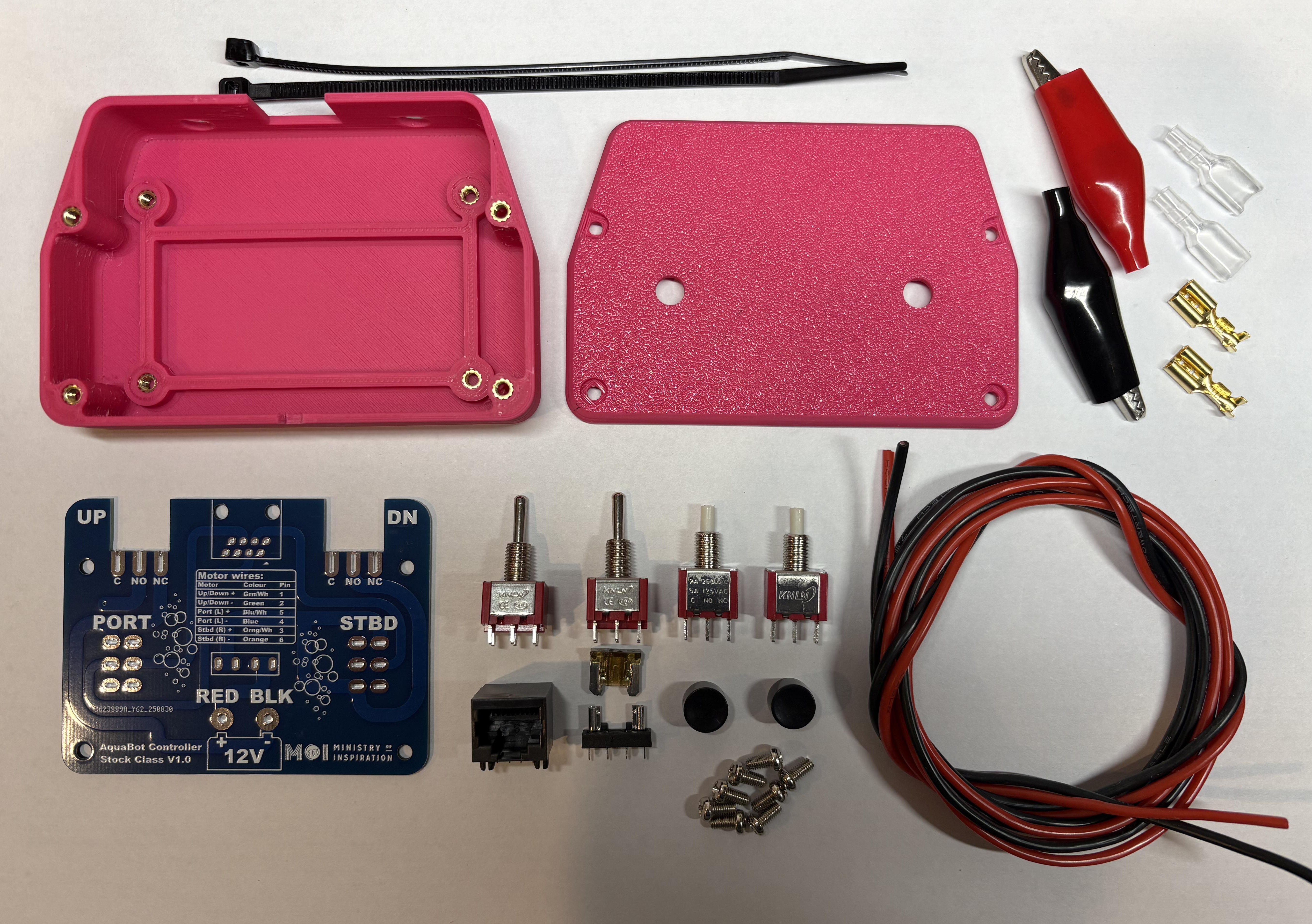
Complete Kit Contents
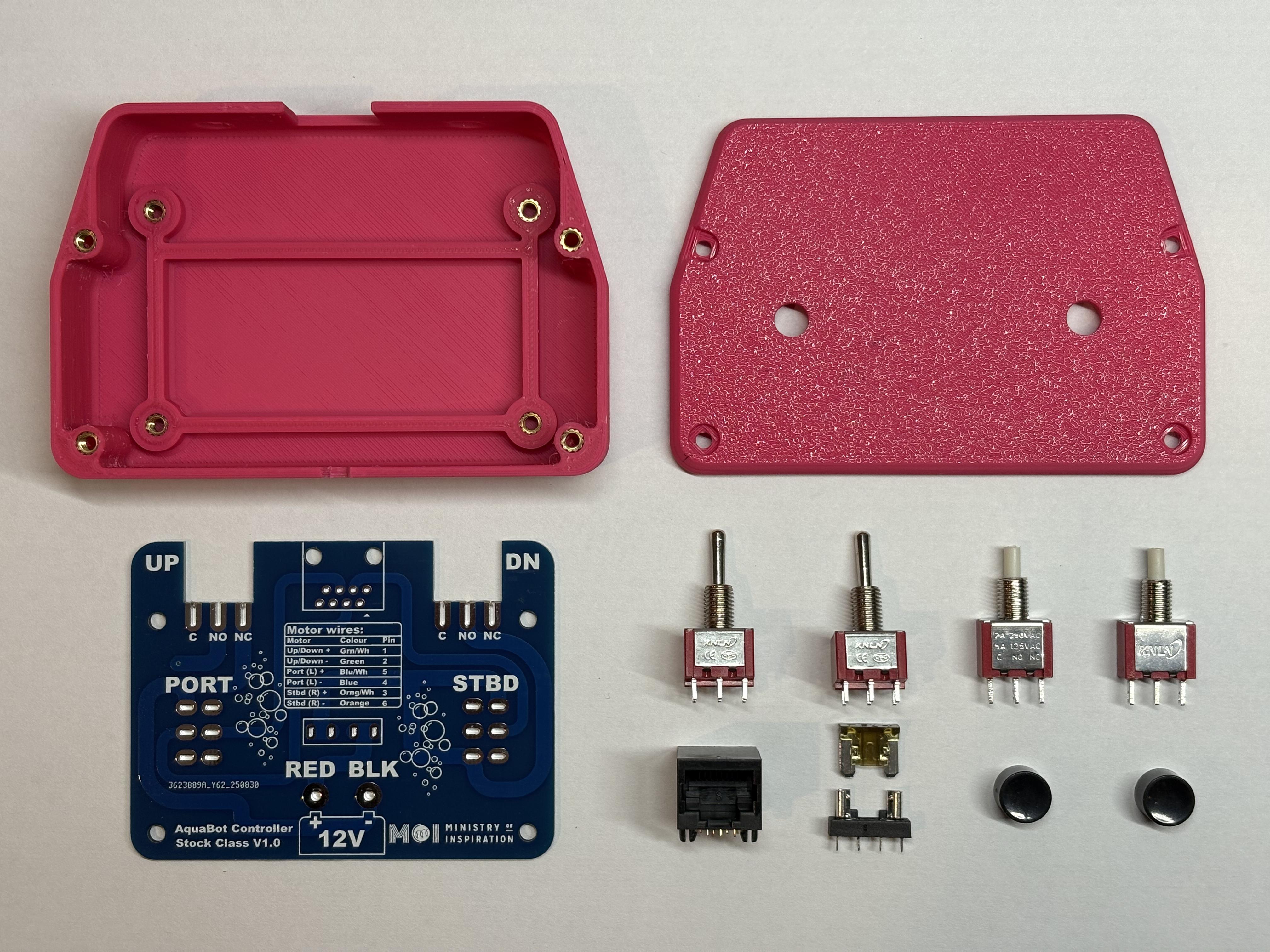
PCB Assembly Parts
Parts Checklist
Let's Build It!
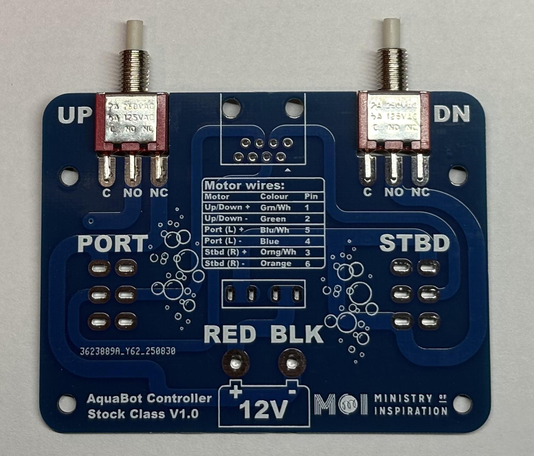
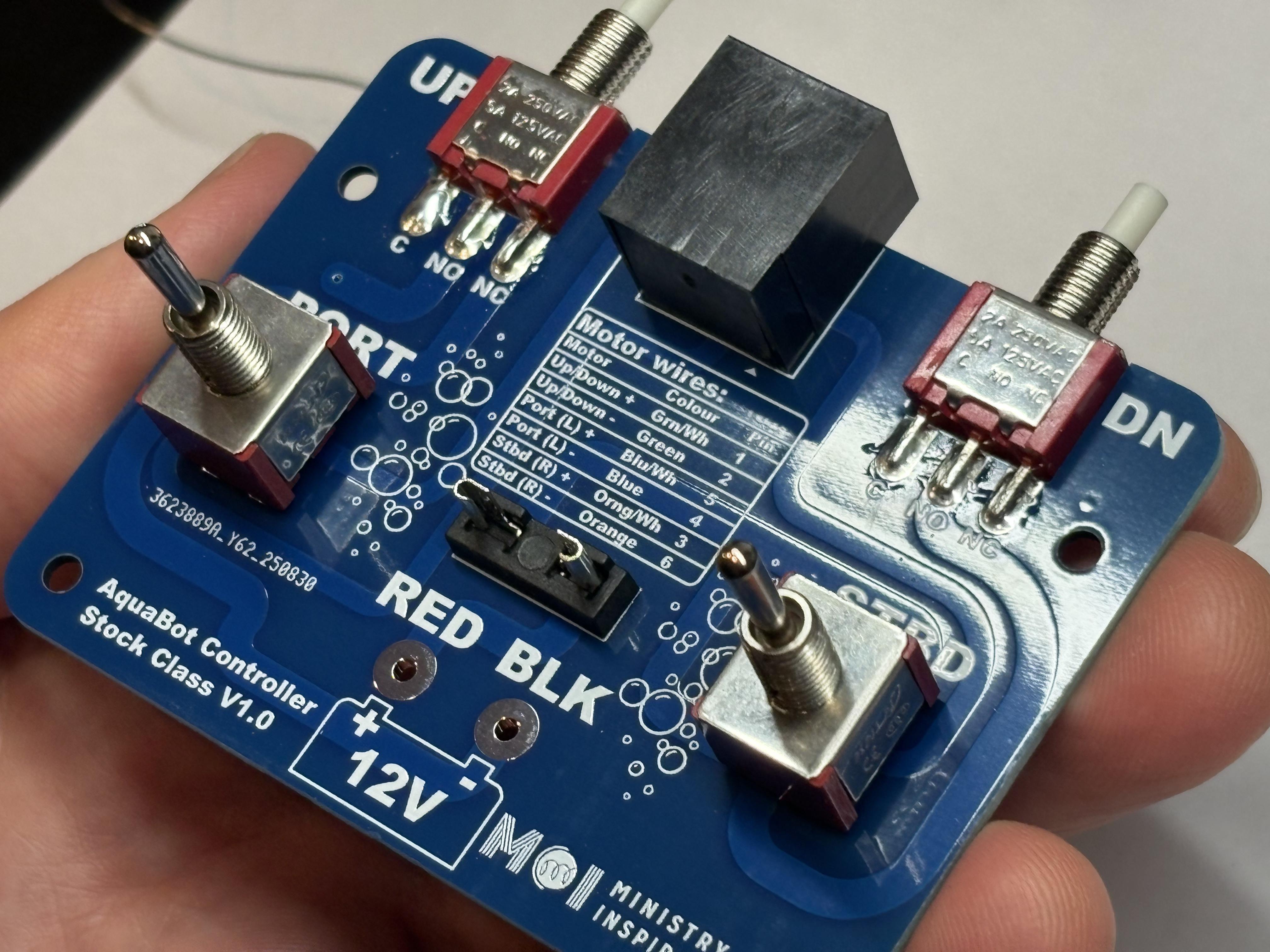
Install Push Button Switches
Push the two push button switches into the PCB slots next to the UP and DOWN labels on the PCB.
Place PCB in Case
Gently place the PCB into the 3D printed case, with the push buttons sliding through the front holes in the case.
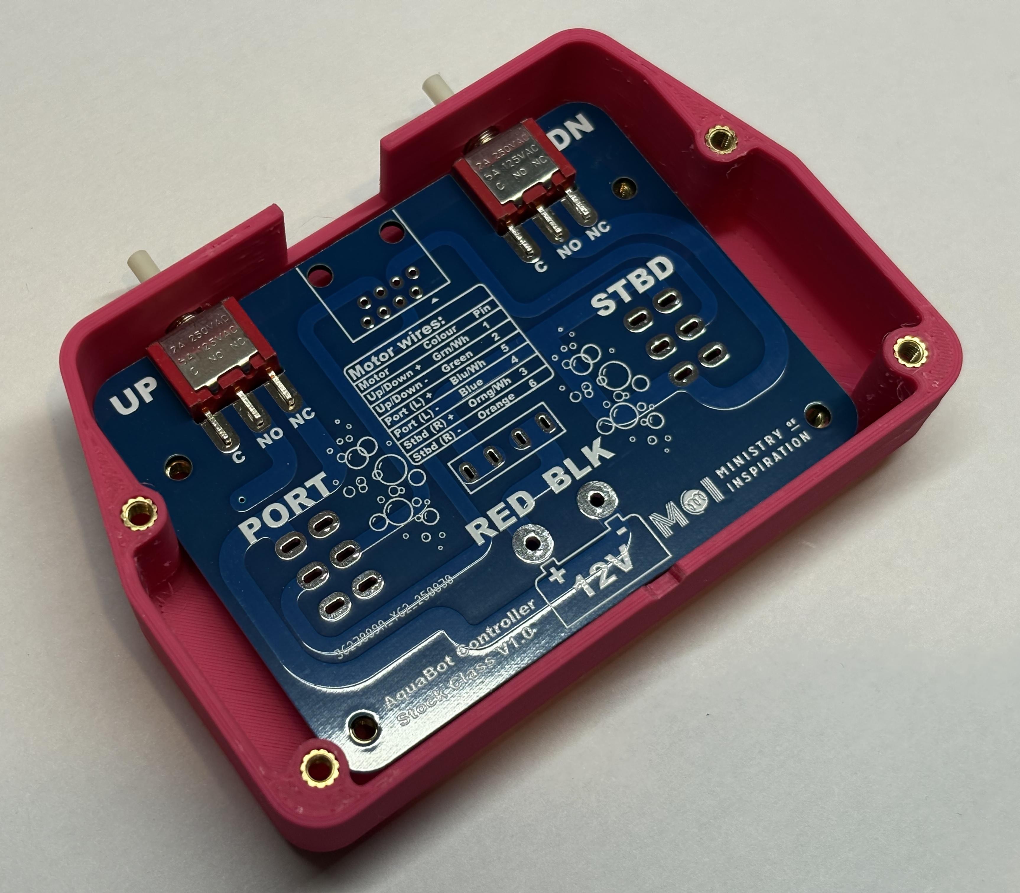
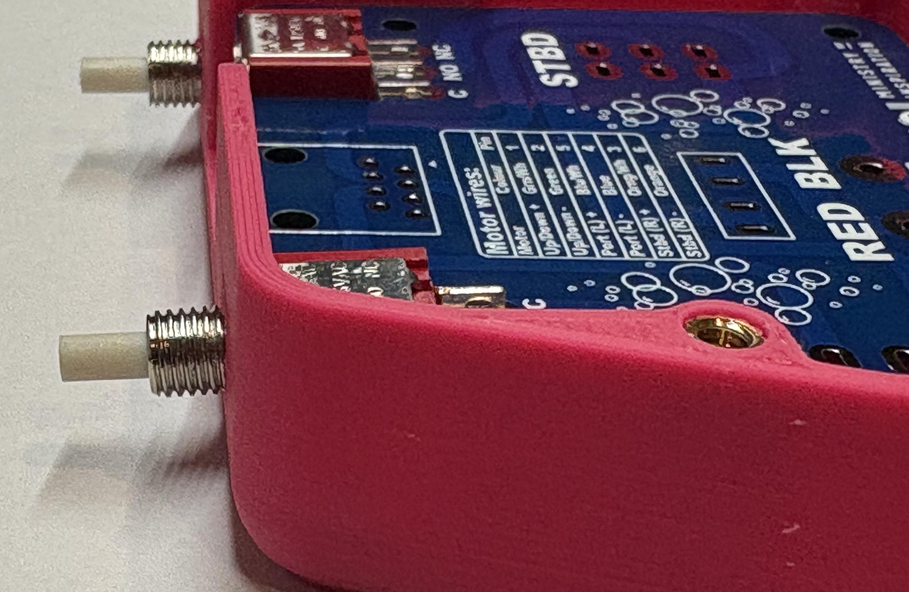
Check Alignment
Check that everything lines up correctly and the buttons are straight. You may want to put some screws in to hold the PCB in place.
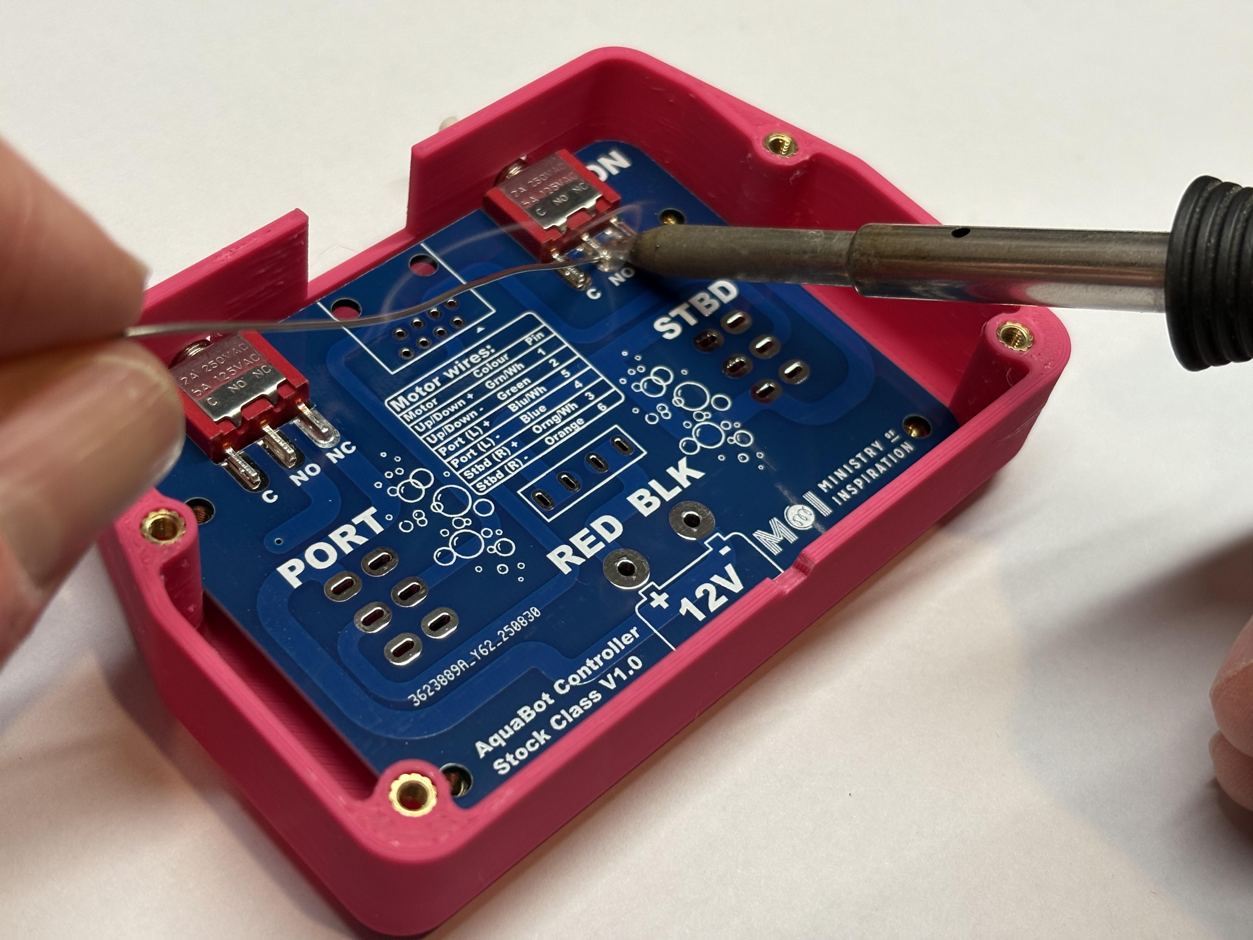
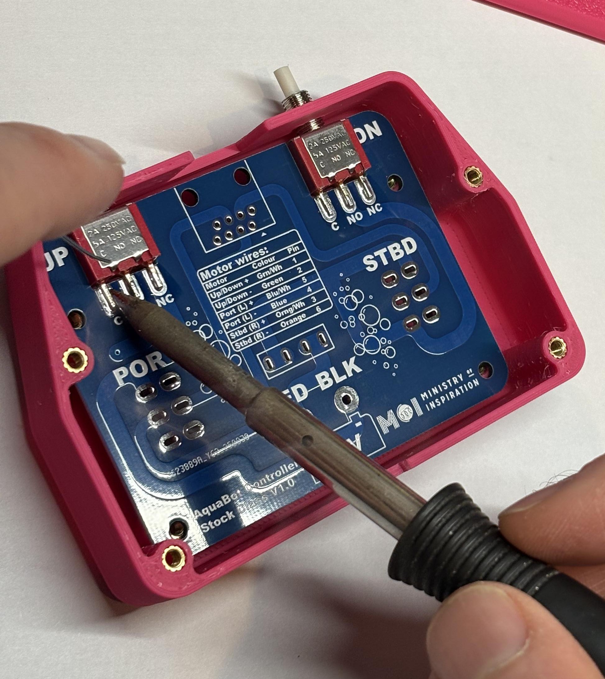
Solder Push Button Switches
Solder the switches in place. Remove the PCB from the case when you have finished.
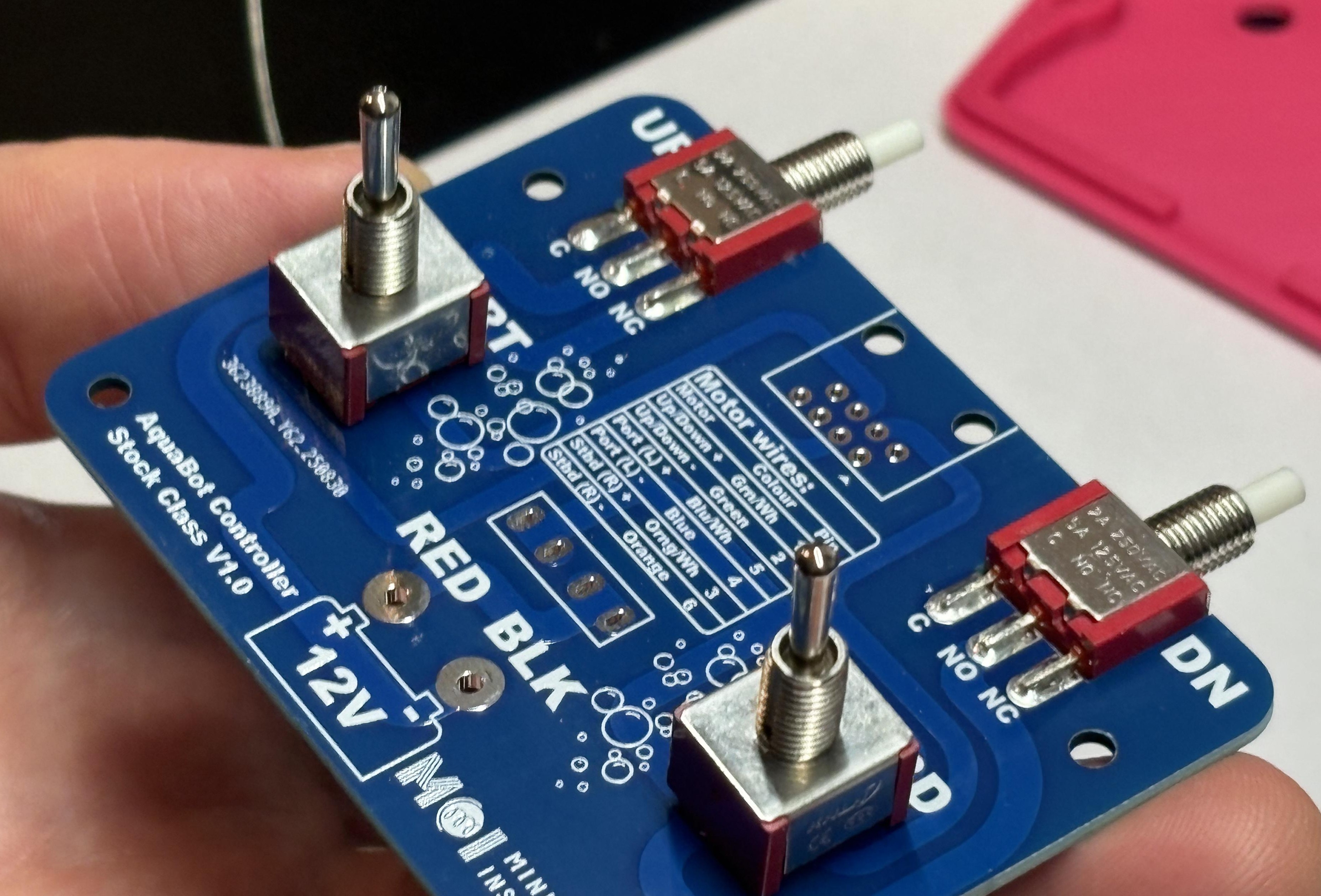
Install Toggle Switches
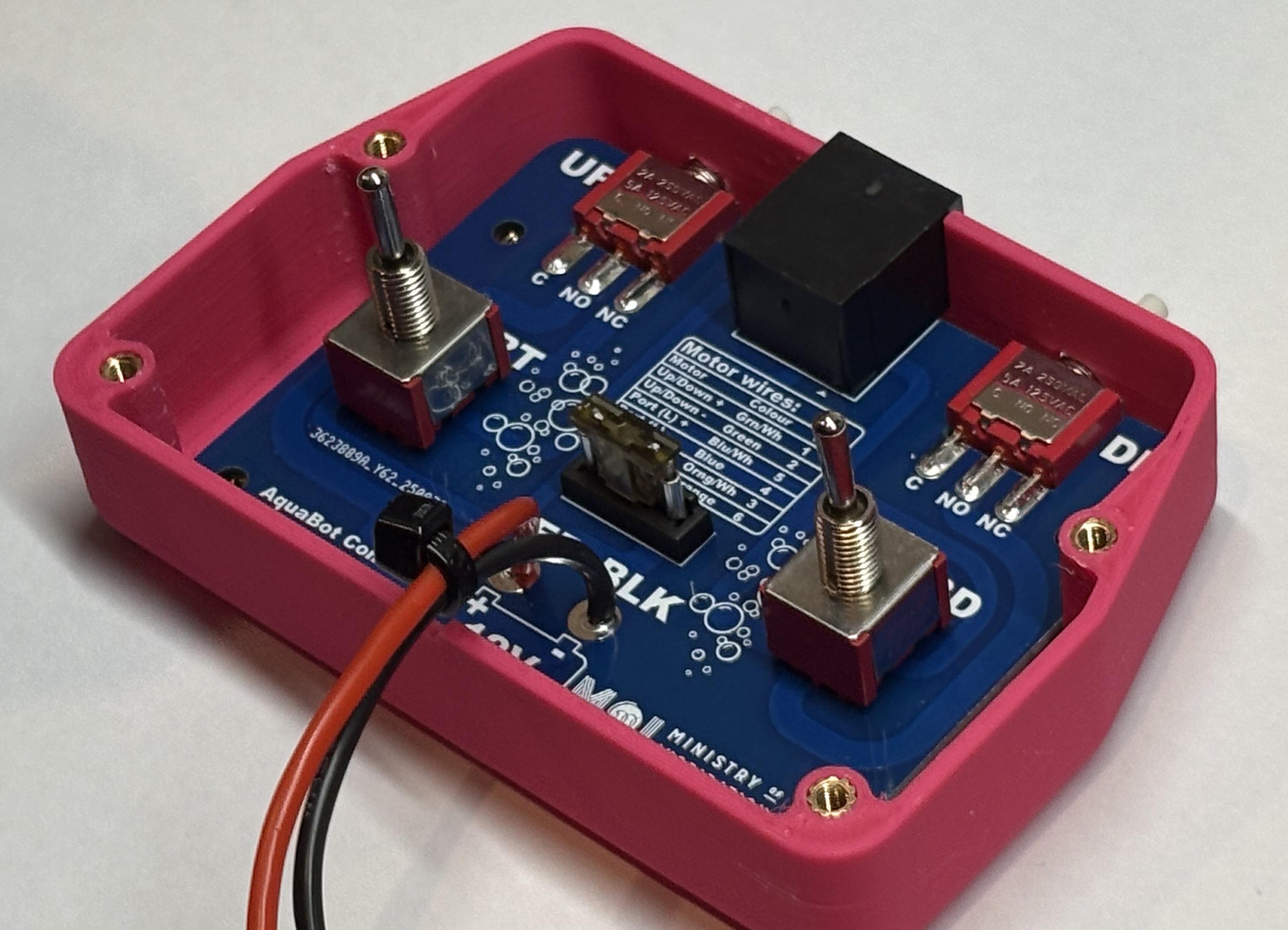
Place the two 3-position toggle switches into the PCB slots next to the PORT and STBD labels on the PCB. It doesn't matter which way around they go for the toggle switches.
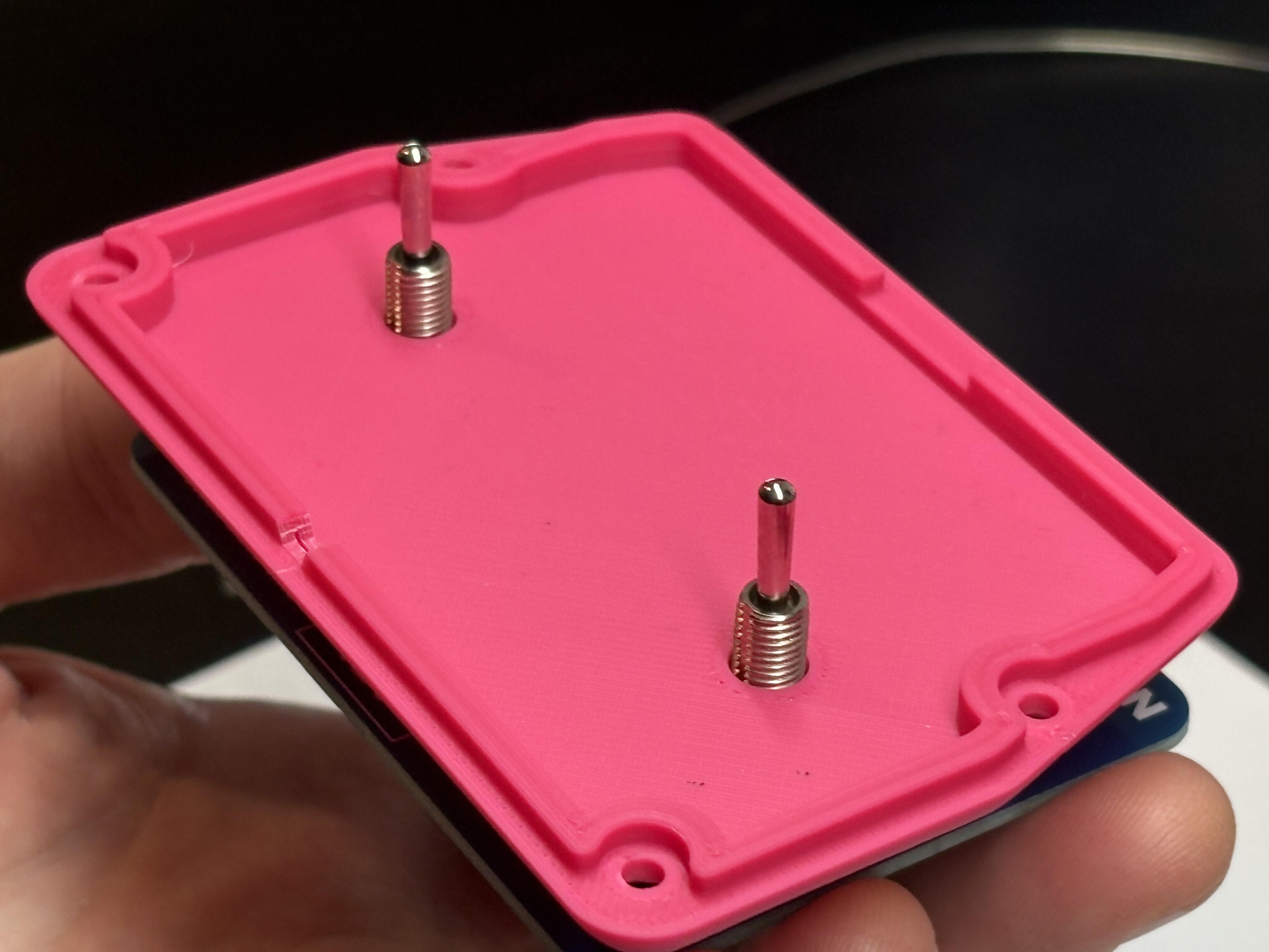
Position Case Lid
Place the case lid on top of the two toggle switches to hold them in the right place, then flip the PCB and lid over and place it on top of the case with the lid facing down.
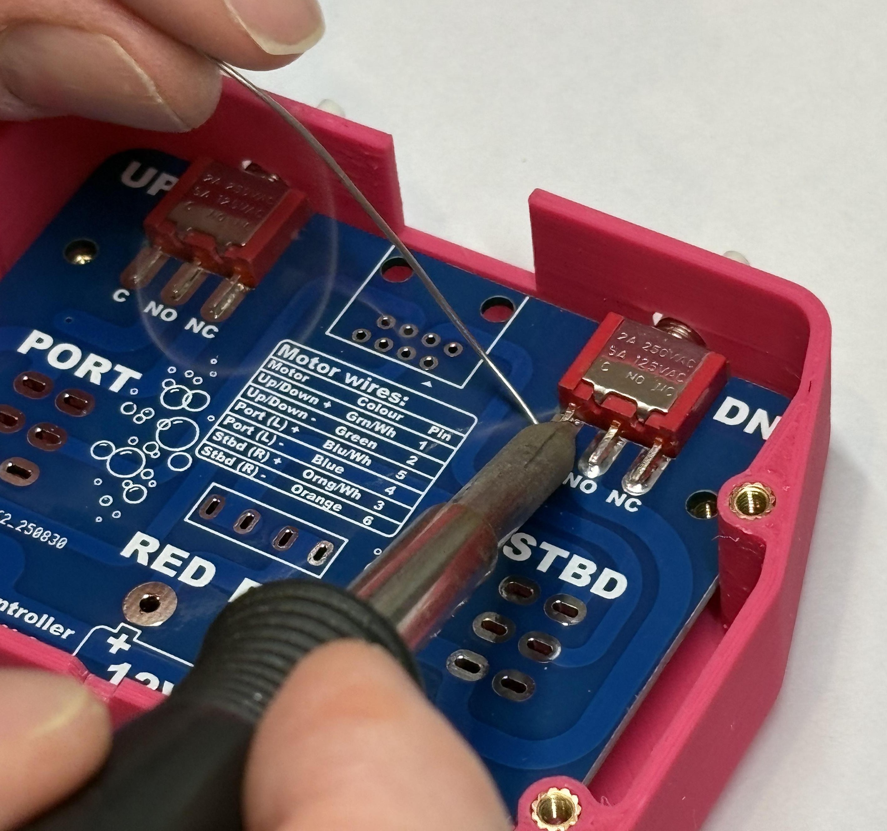
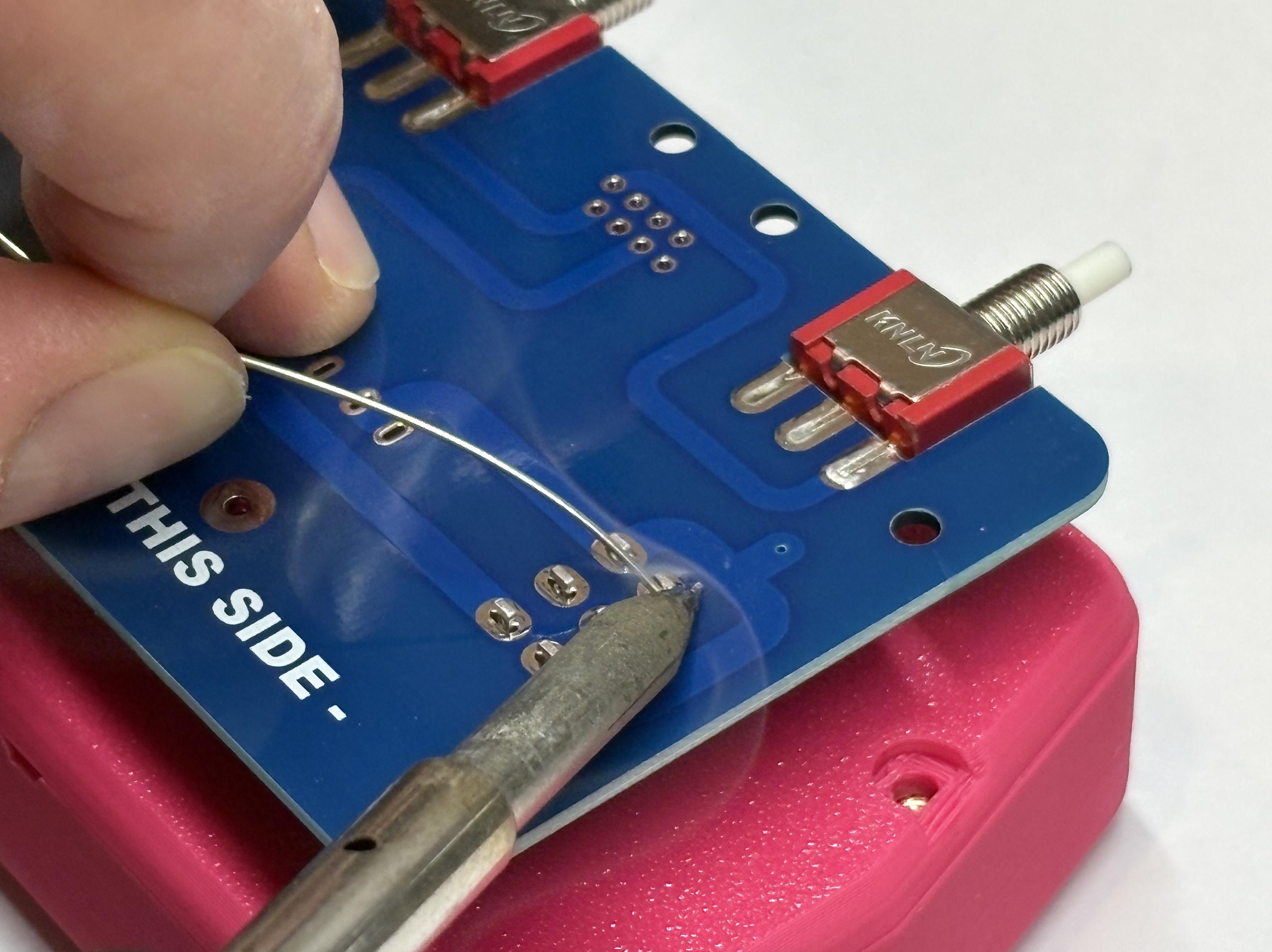
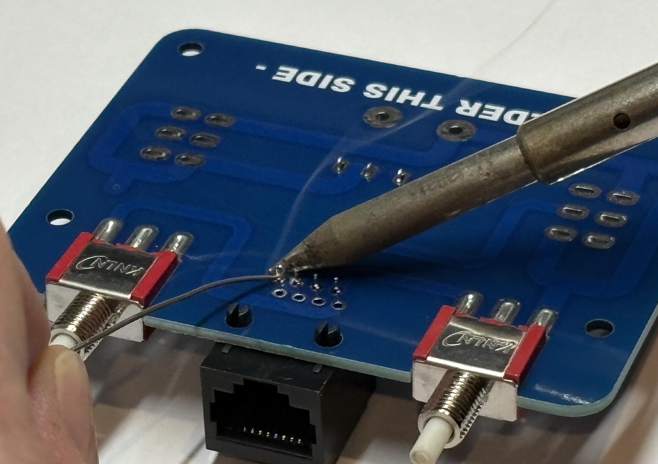
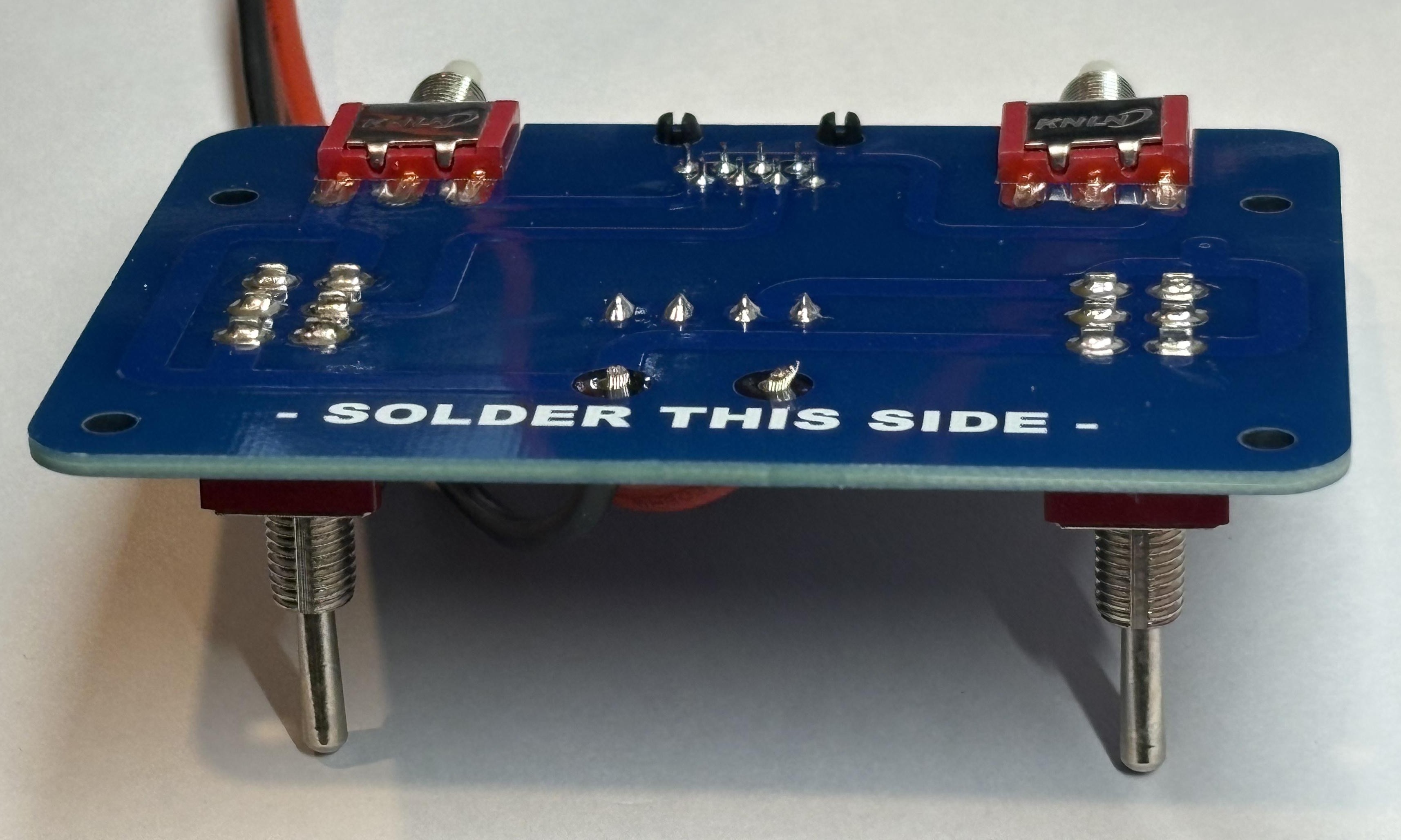
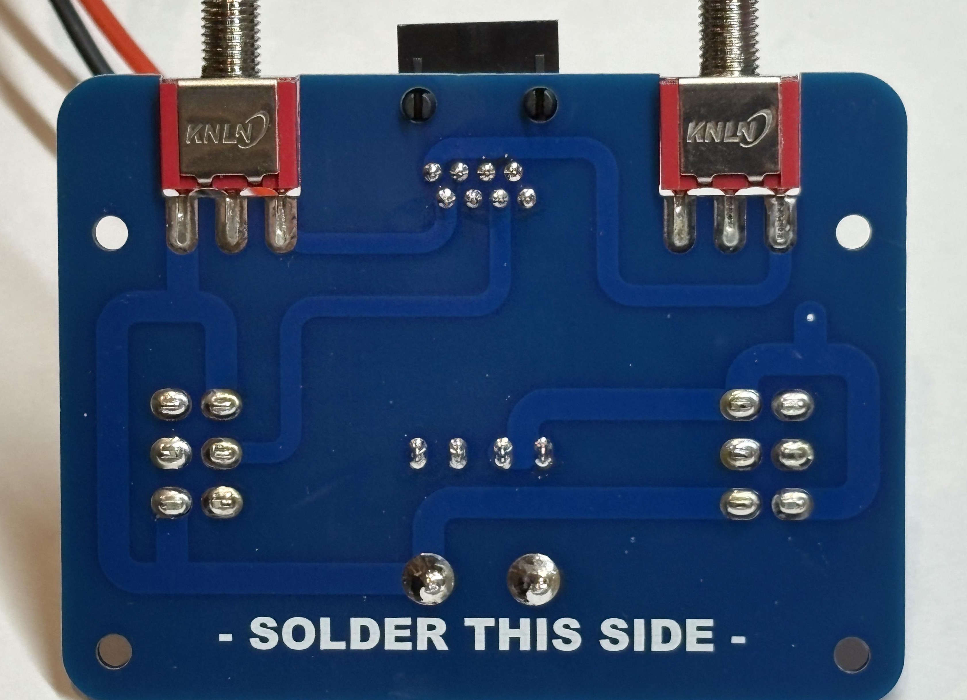
Solder Toggle Switches
Holding the PCB flat (you might want a friend to help you), solder in the toggle switches. Sometimes it helps to just solder one leg of the switch and then lift the board up to check that it is straight.
Install RJ45 and Fuse Holder
Snap in the RJ45 connector and the fuse holder, they should stay in place by themselves.
Solder RJ45 and Fuse Holder
Flip the board over and solder in the RJ45 connector and the fuse holder.
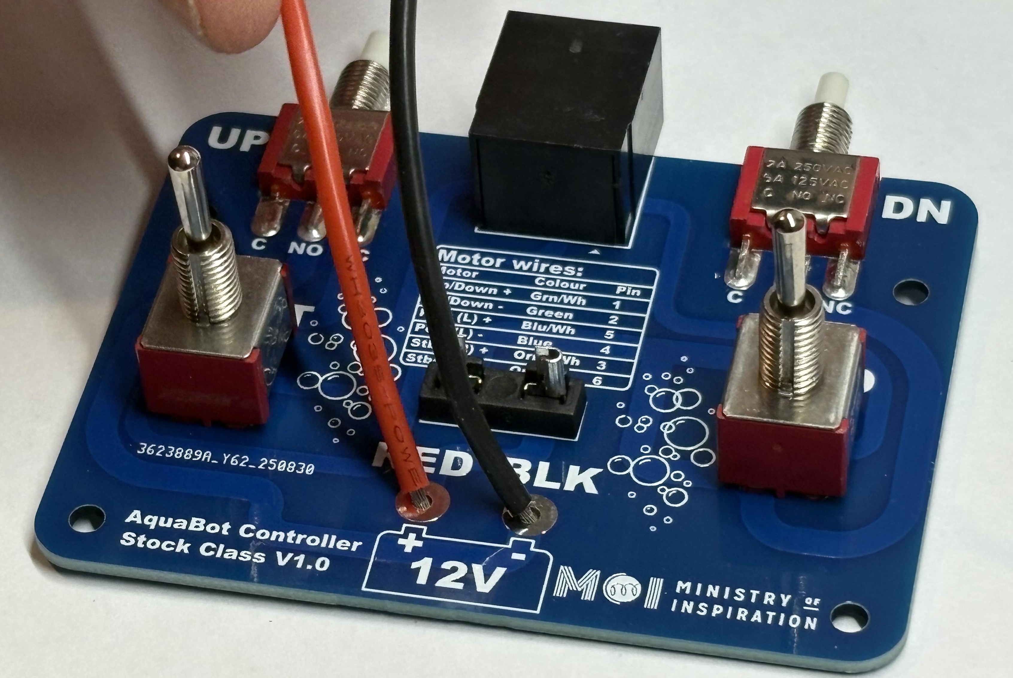
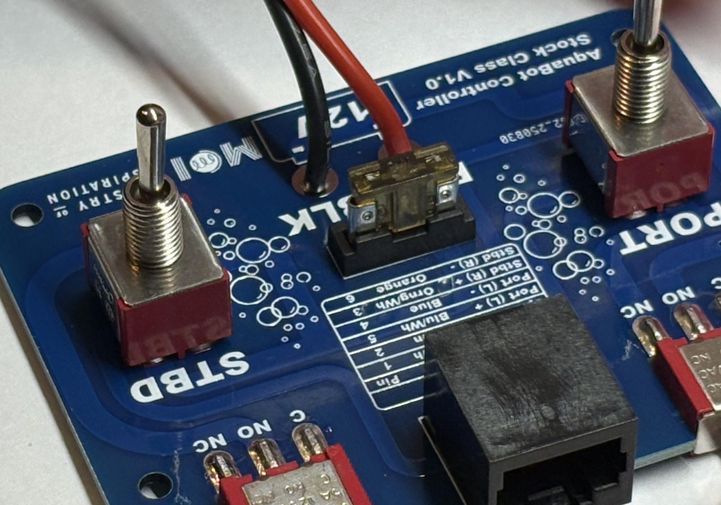
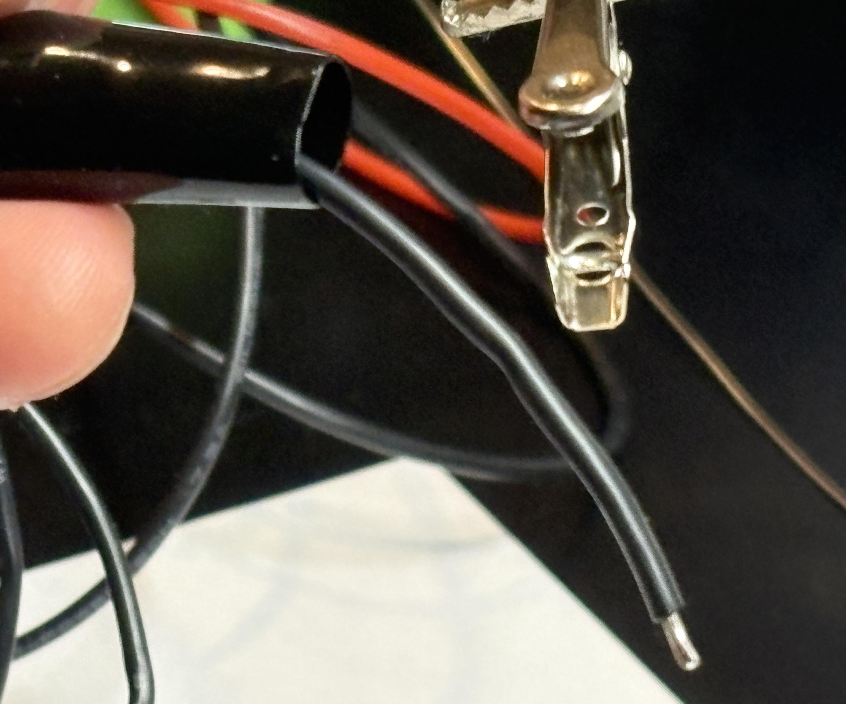
Prepare Battery Wires
Strip about 5mm of insulation from the ends of the wire for the battery connection, twist the ends of the wire if you need to get all of the wire strands straight. Carefully push the wires into the PCB holes.
Insert Battery Wires
Carefully flip the PCB over, holding the wires in place, you may want to put them in one at a time if they keep slipping out.
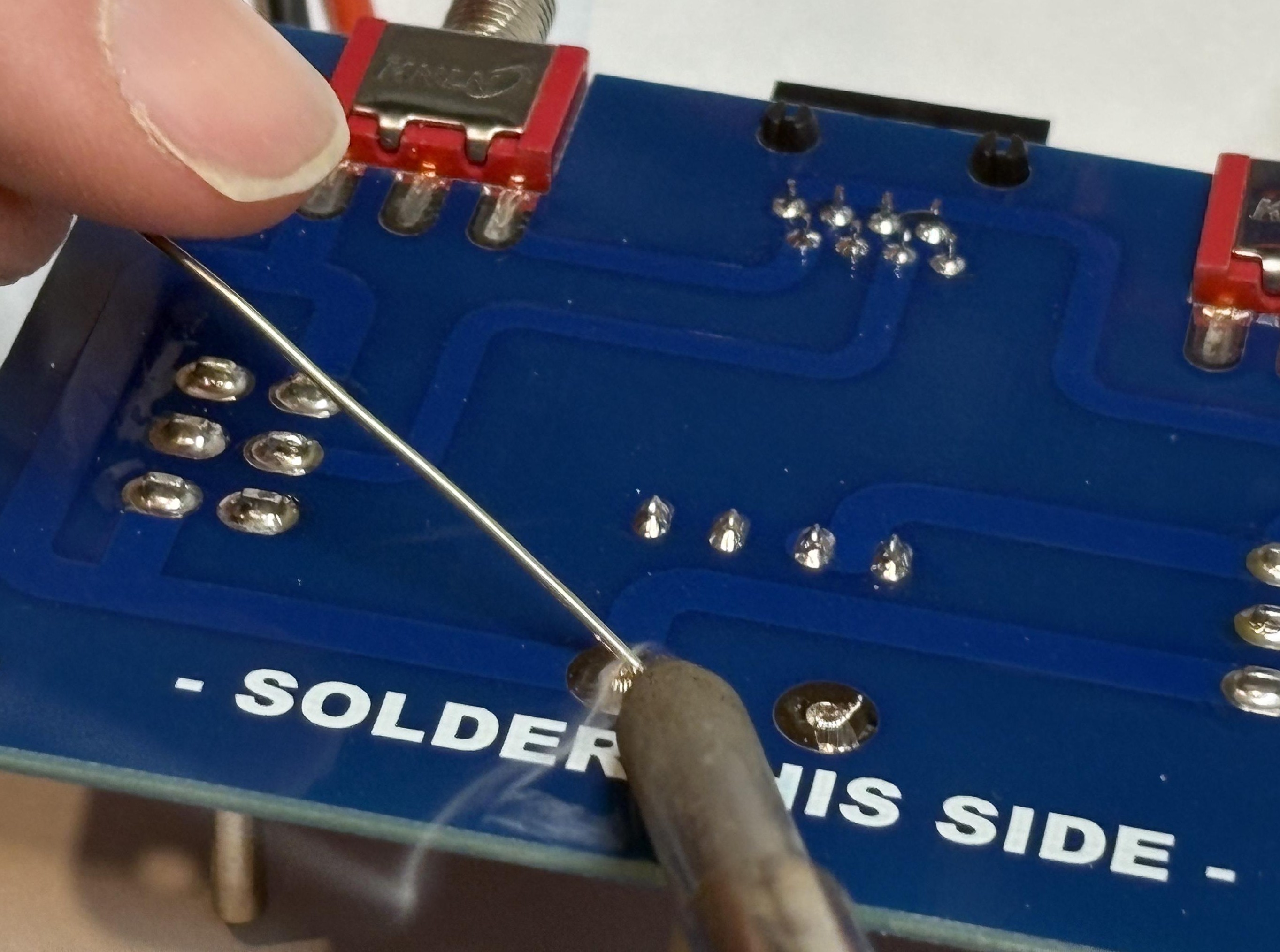
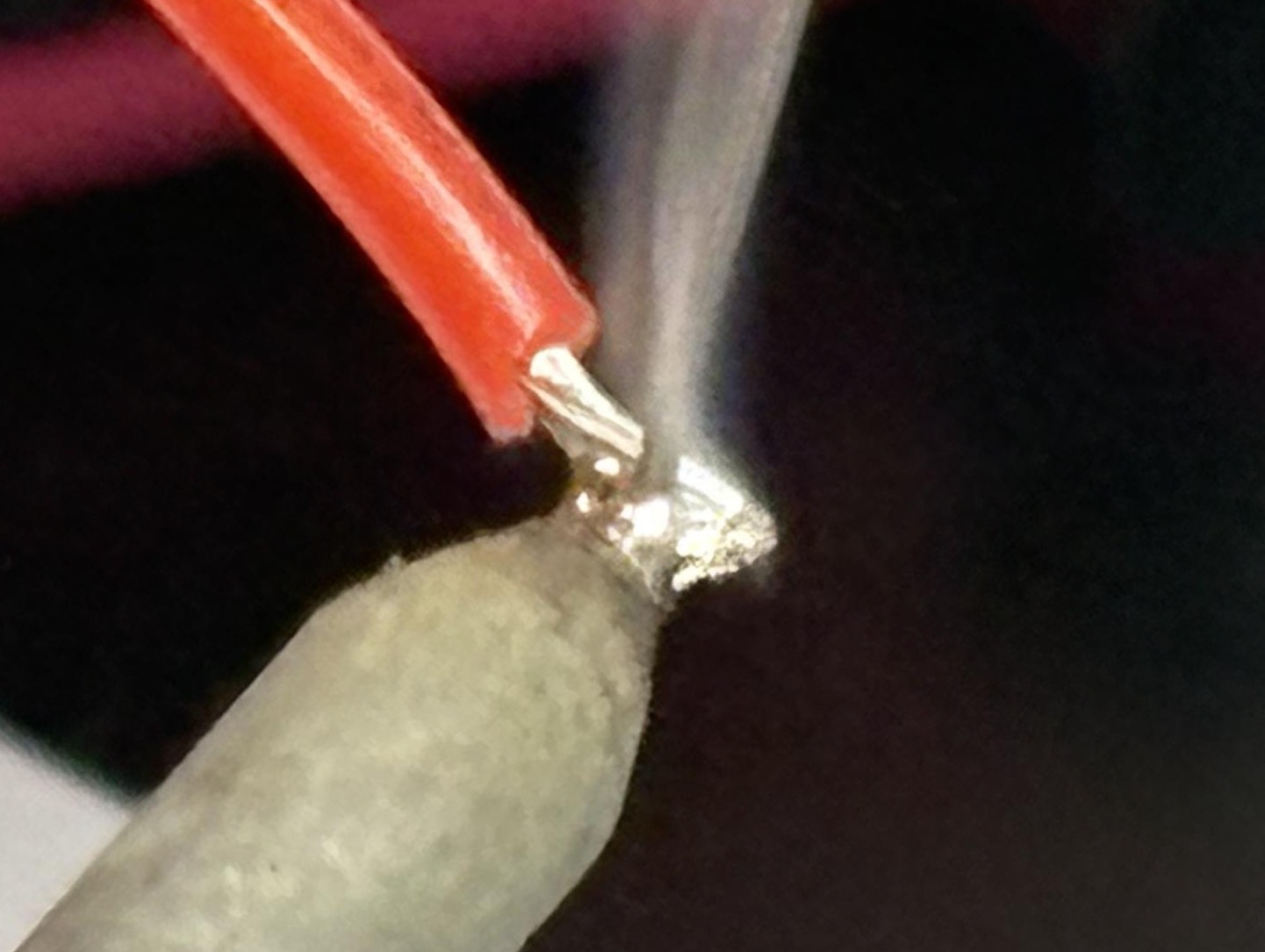
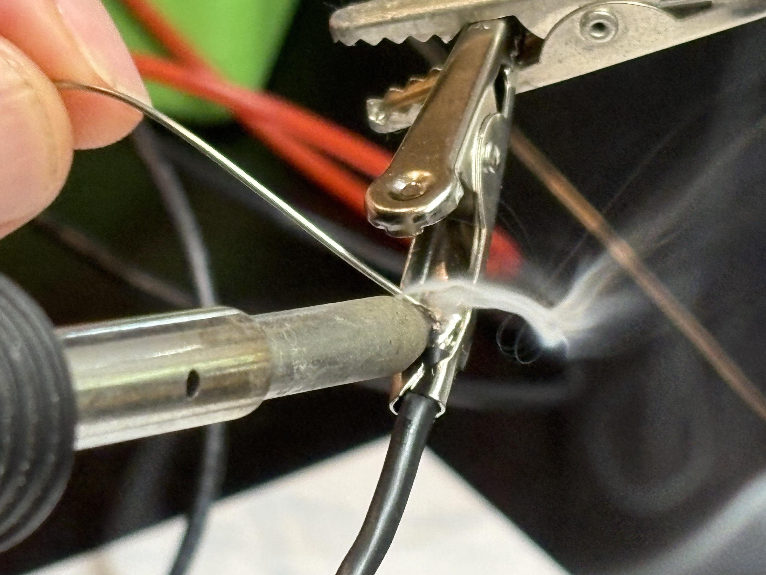
Solder and Trim Wires
Solder the wires in place and trim the ends back if they are sticking out a long way.
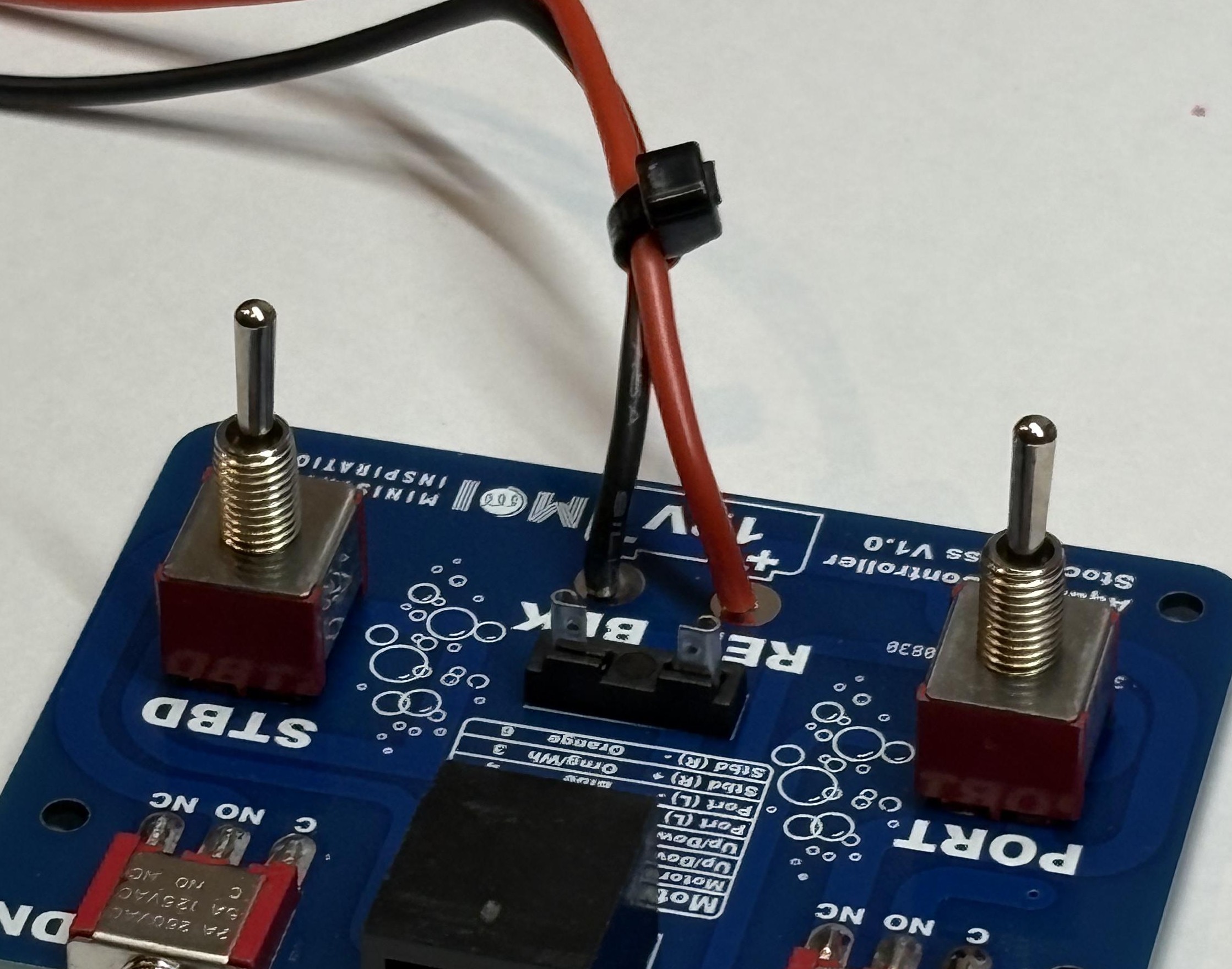
Secure Wires with Cable Tie
Zip up a cable tie around the wires about 25mm from where they are soldered into the PCB. This will stop the wires from pulling against the soldered joint so that they don't break off while you are winning the competition!
Install Fuse
Push the fuse into place in the fuse holder.
Secure PCB in Case
Place the PCB back into the 3D printed case, and secure it with 4 screws.
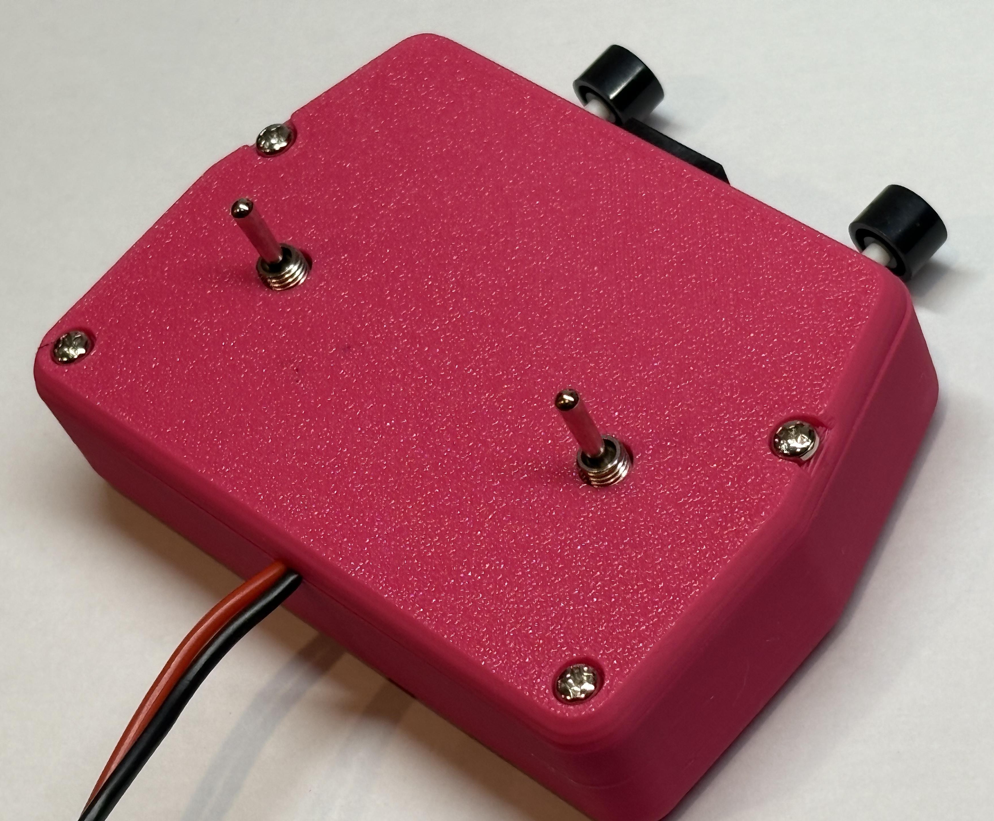
Close the Case
Make sure the wires are sitting over the slot in the top of the case, put the lid on and secure it with 4 screws.
Choose Your Battery Connection
You can choose between two types of battery connections. Pick the one that works best for your setup!
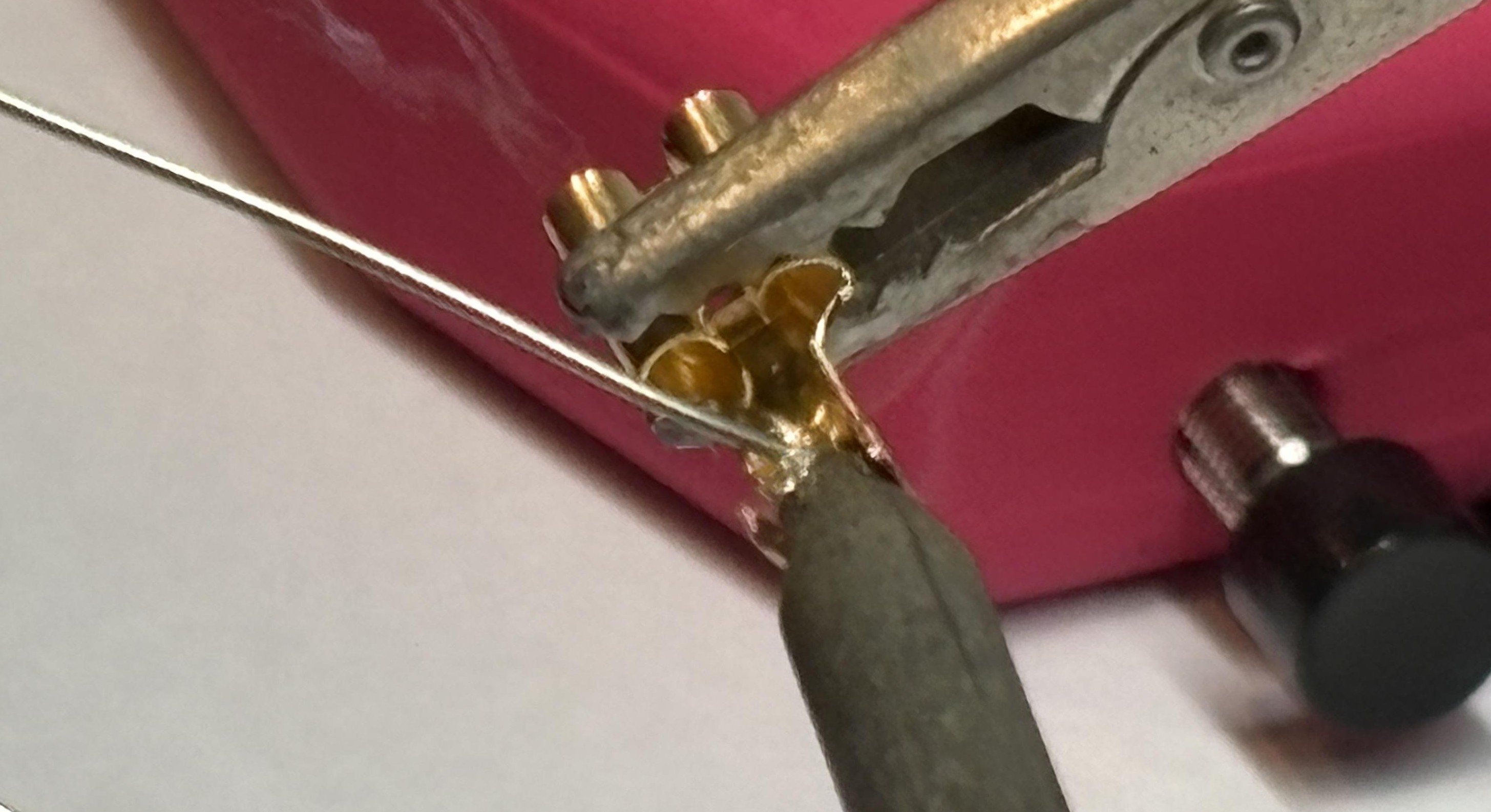
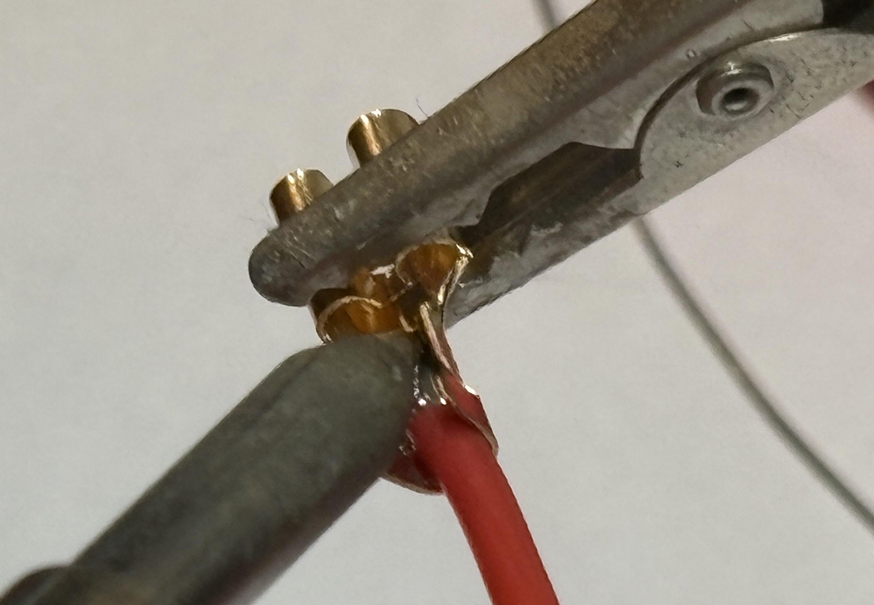
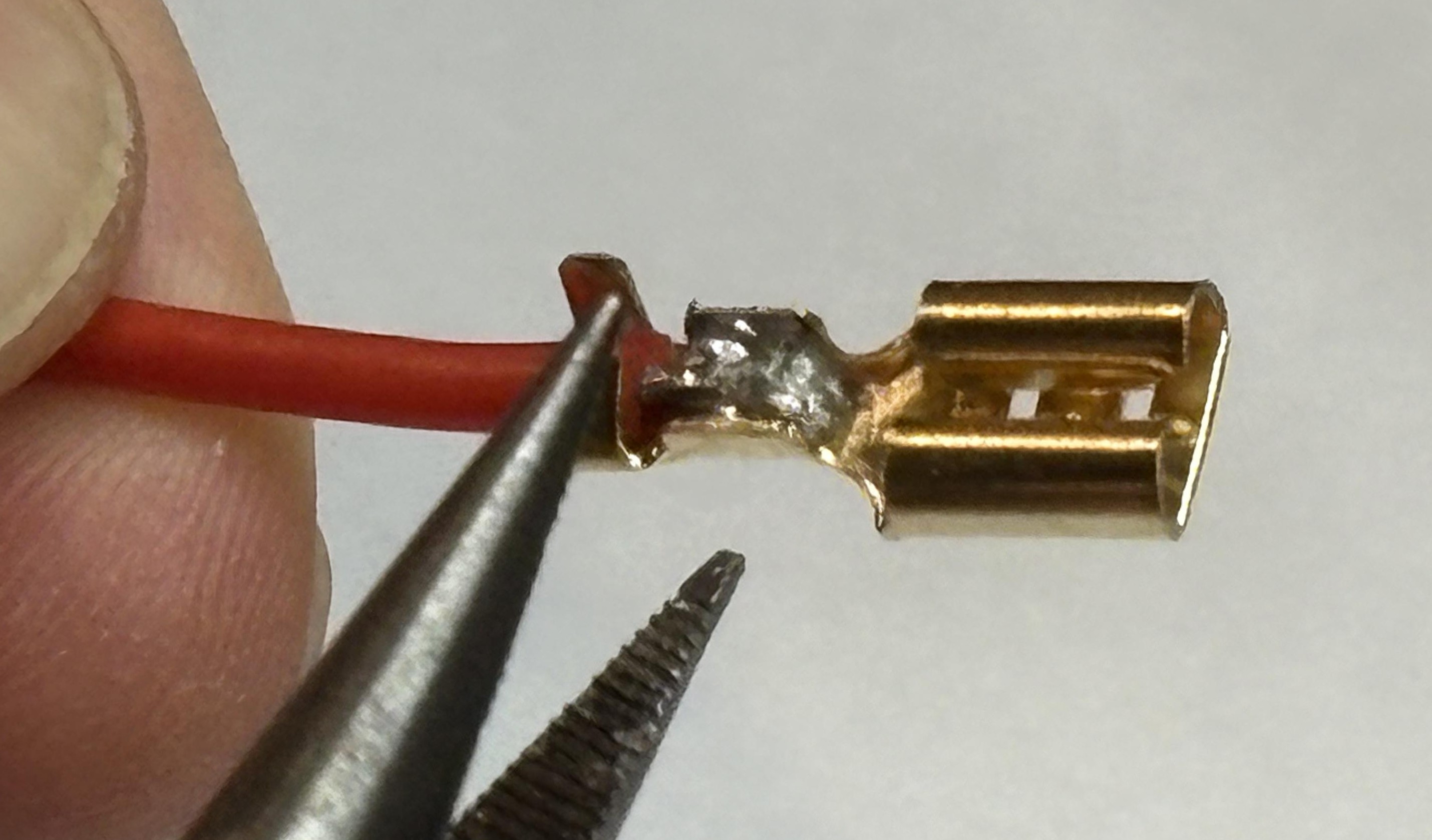
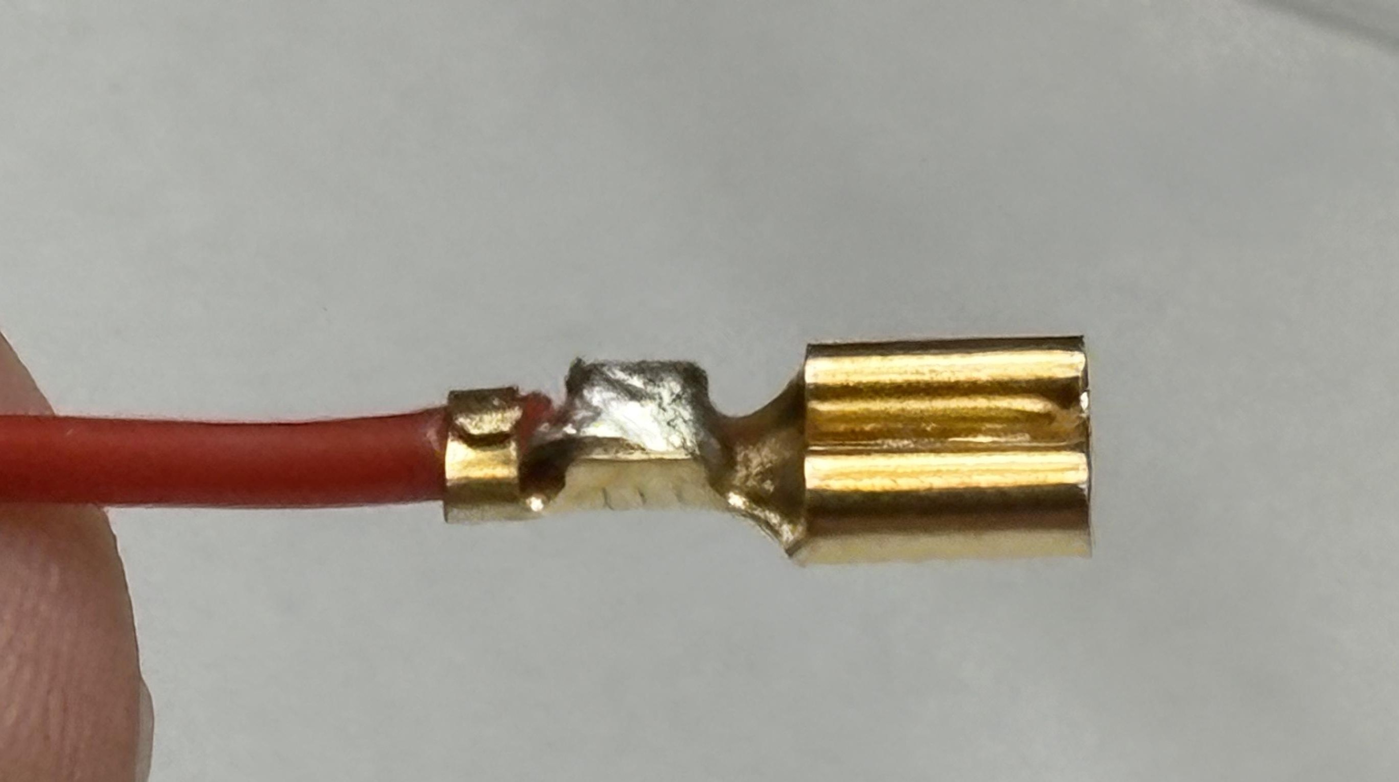
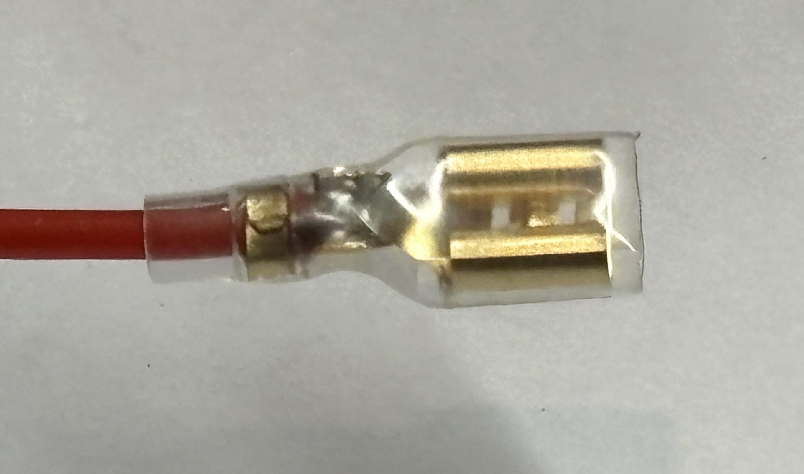
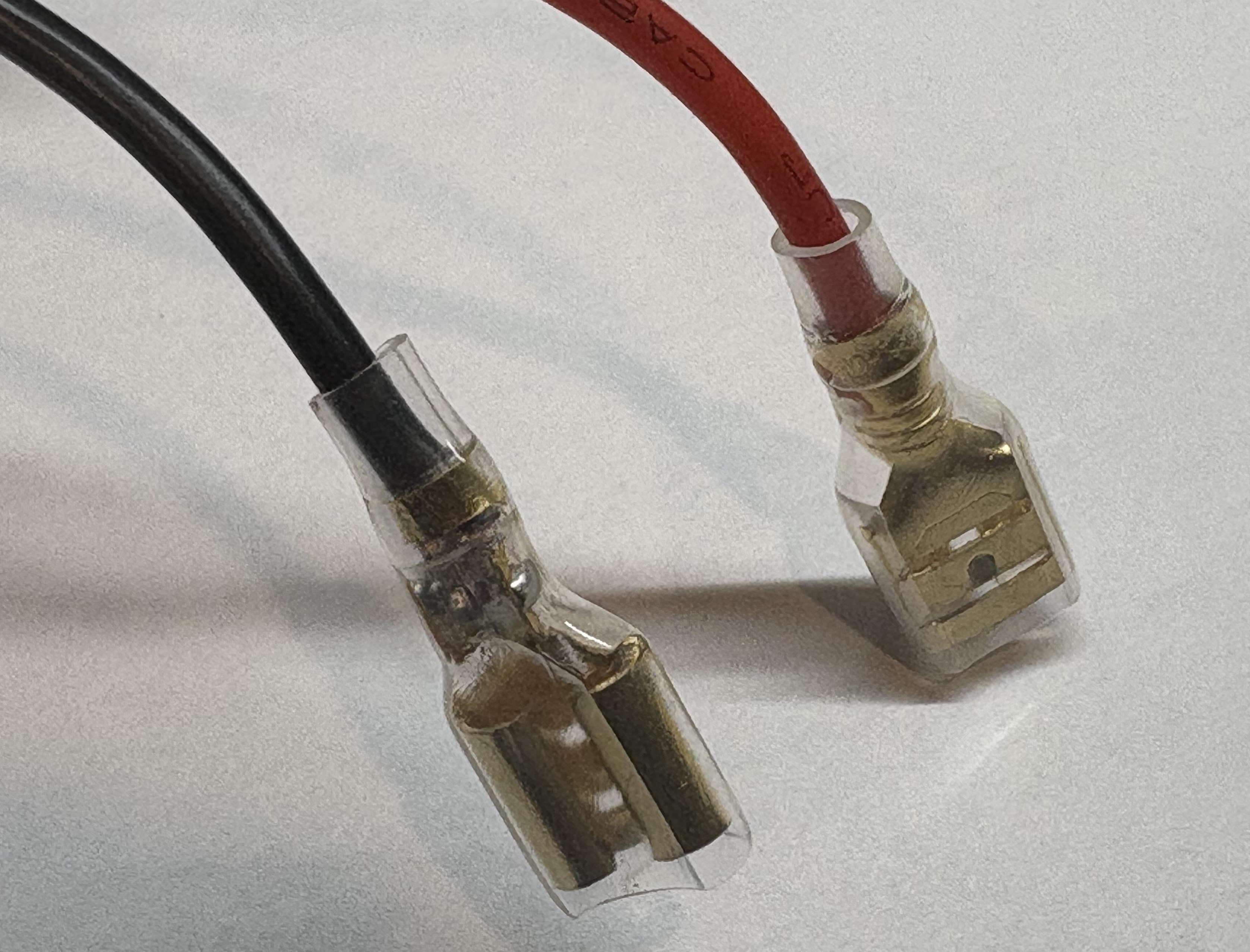
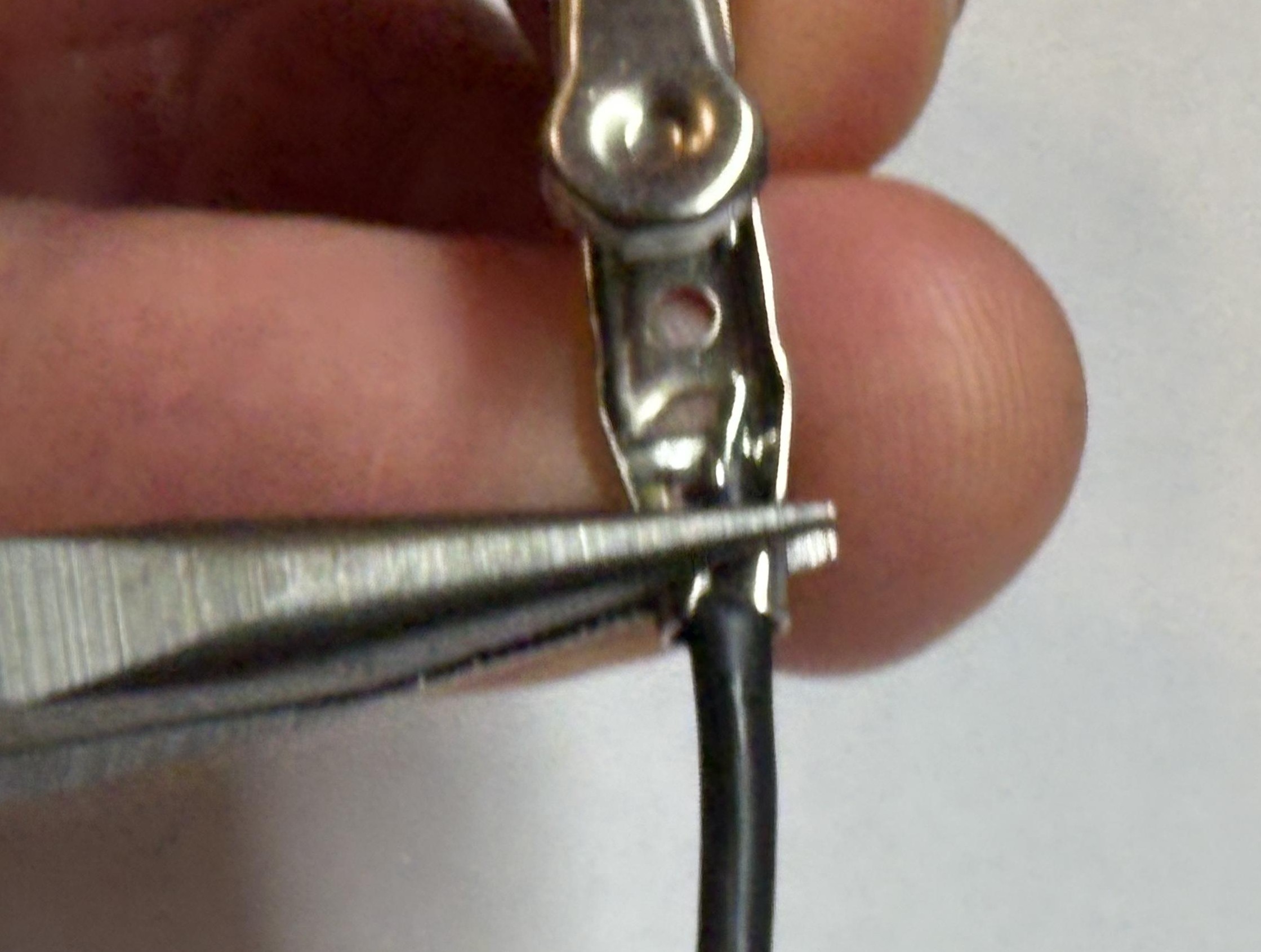
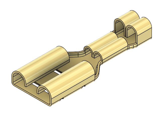 Spade Connectors
More permanent and secure connection
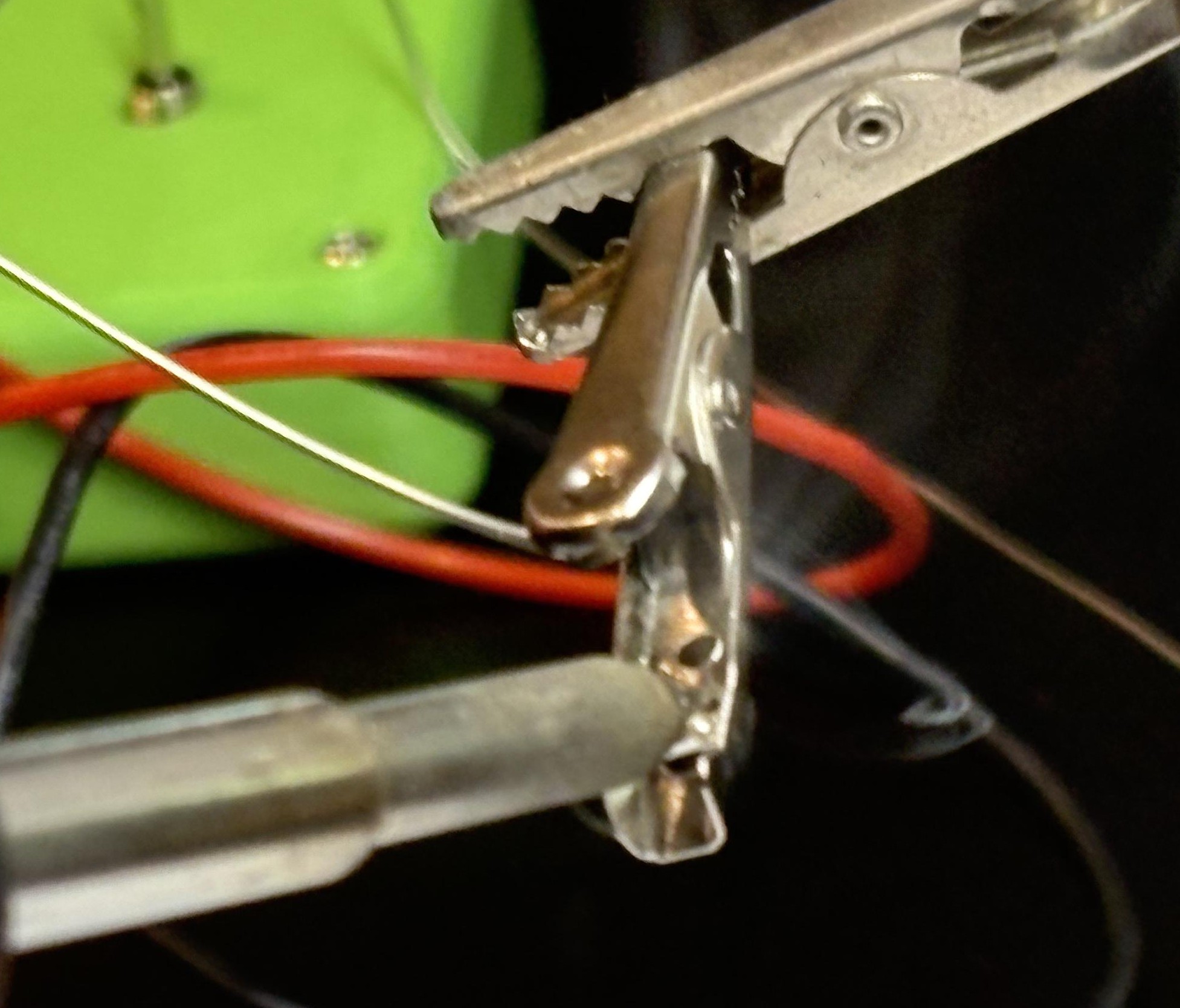
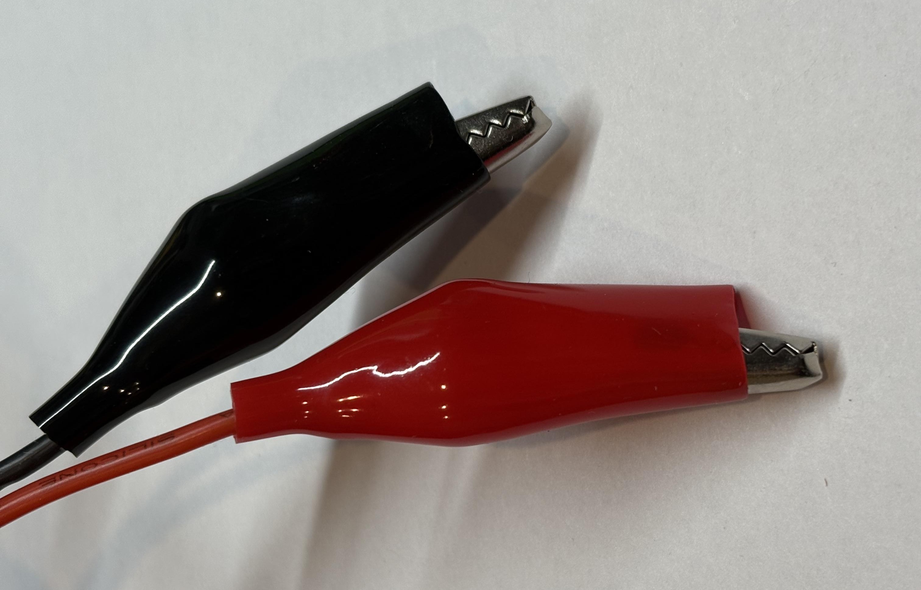
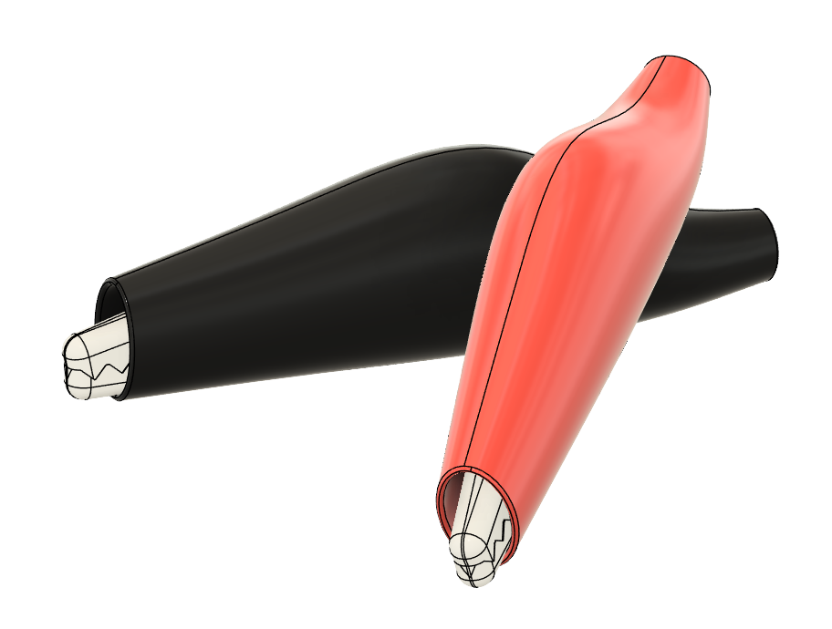 Croc Clips
Easy to connect and disconnect
Testing Your Controller
Now let's test your controller to make sure everything works perfectly!
Set Up Multimeter
Using a digital multimeter, set the measurement to continuity (the Ω symbol). Touch the leads of the multimeter together and check that the reading goes to 0 (or close to 0).
Test Controller Leads
Connect the two multimeter leads to the controller leads, the reading should go to infinity (sometimes shown as OC on the multimeter).
Test Buttons and Switches
Press both of the buttons, one at a time, then the switches one at a time. The meter should not change reading.
Test with AquaBot
Connect the controller to your AquaBot and complete the same check again. This time the reading should be infinite when no buttons are pressed, and when you press a button the reading should go to about 5 ohms.
Additional Resources
Download 3D models for printing your case and access the schematic files!
3D Printable Cases
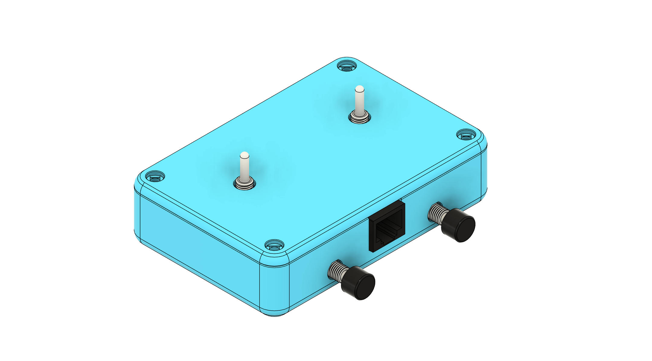
Basic Enclosure
Simple, easy-to-print case design perfect for beginners.
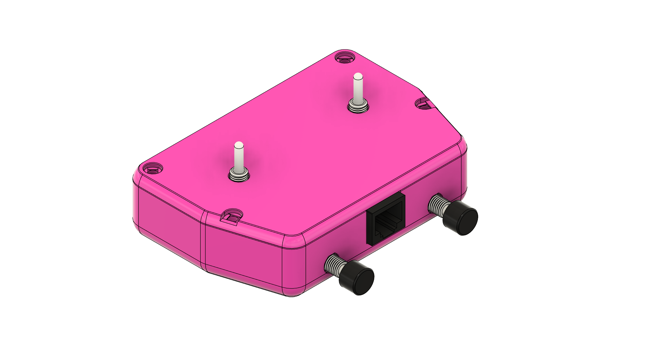
Angled Enclosure
Ergonomic angled design for comfortable controller handling.
Electronics & Schematics
Controller Schematic
Complete circuit diagram showing all connections and component values.
PCB Design Files
Altium Designer project files for advanced users who want to modify the PCB.
3D Printing Tips
Print Settings
- Layer Height: 0.2mm
- Infill: 0% (designed for hollow printing)
- Supports: Not required
Materials
- PLA: Recommended material - easy to print and perfect for this project
Assembly Hardware
- M3 x 4mm heat set inserts x8 required
- M3 x 6mm screws x8 required
- No sanding required - parts fit perfectly as printed